Author: tanya

  • Export Packing of Drill Bits and Rods: What to Write Into Your Purchase Order

    Export Packing of Drill Bits and Rods: What to Write Into Your Purchase Order

    Nothing ruins a good price faster than a shipment of rusted threads and bent rods. Drill bits and rods are heavy, hard, and shaped exactly wrong for freight: pointed, threaded and prone to chipping each other. Packing is therefore not administration – it is part of the specification, and it belongs in the purchase order, not in an email two days before loading.

    What kills a shipment in transit

    • Moisture. Sea freight crosses climates. Steel in a container sweats, and a threaded joint with surface rust is a joint that will never seat properly again.
    • Impact. Bits tipped into a loose carton chip each other’s carbide on the first bump. Missing buttons are the most common transit claim in this industry.
    • Bending. Rods that are not supported or strapped bend under their own weight during handling. A rod with a slight bow drills an oversized, wandering hole.
    • Mixed sizes. Loose parts of similar diameter in one box are counted wrong at destination and used in the wrong application.

    How bits should be packed

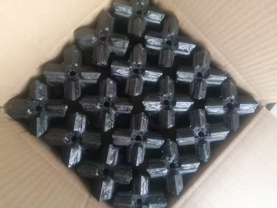
    A properly packed bit carton has three features: the bits are separated from each other, the cutting ends cannot touch anything hard, and the threads are protected.

    • Bits are nested in a fitted carton, a moulded insert or a wooden plate so every bit sits in its own pocket.
    • Caps or sleeves over the shank thread, and a light oil or anti-rust film on all machined surfaces.
    • VCI paper or a desiccant bag inside the carton for long sea voyages.
    • Carton or case marked with the part number, diameter, quantity and gross weight – in figures, not only in words.

    For heavier or higher-value bits, a wooden case with internal dividers is normal and usually worth the extra cost; it is also the format most likely to arrive undamaged after three transshipments.

    How rods should be packed

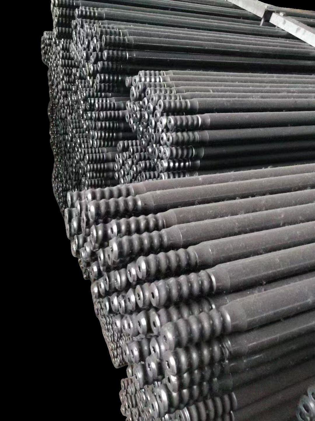
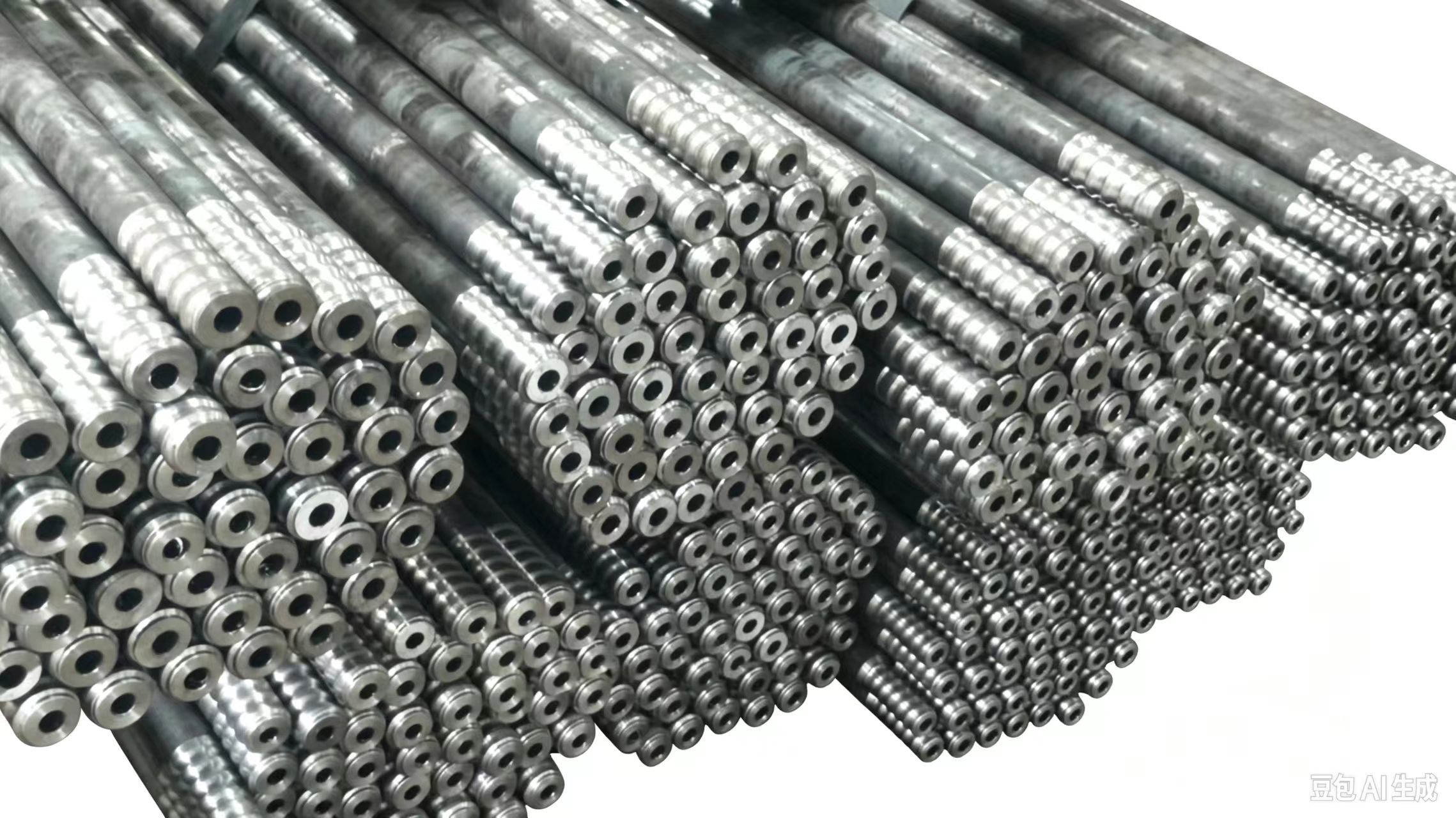
    Rods are dense, so weight – not volume – is normally the limiting factor in a container. The packing job is to stop them bending and to keep the machined ends away from impact:

    • Bundles strapped with steel banding at several points along the length, with timber or plastic spacers so the straps cannot crush the rod surface.
    • Threaded or tapered ends protected with plastic caps or a wooden end board.
    • Bundles blocked and braced inside the container so they cannot shift during a sea passage.
    • Bundle length chosen to suit the container: rods that just fit are far easier to secure than rods with half a metre of slack.

    Packing clauses to put in the PO

    Copy these into your order and the argument at destination largely disappears:

    1. Packing standard and material: carton, wooden case or strapped bundle, with internal separation between parts.
    2. Thread and taper protection: caps required, oil film required, no exposed machined surfaces.
    3. Quantity per carton and per bundle, and total quantity per size – stated in figures.
    4. Marking: part number, diameter, quantity, net and gross weight, and your own shipping marks.
    5. Documentation: packing list with dimensions and weights, and photos of the packed goods before loading.
    6. Preservation period: how long the goods must survive in storage, which decides whether VCI paper and desiccant are needed.
    7. Inspection: whether you or your agent may inspect before the container is sealed, and whether a sample of each size must be included.

    Two clauses that are often forgotten and worth adding: a requirement that bits of different diameters are packed separately, and a requirement that the packing list agrees exactly with the physical count. Counting discrepancies are the most common commercial dispute in this trade, and they are entirely avoidable.

    Receiving the shipment: first hour

    Before the container is emptied, photograph the load as found, check the strapping and look for signs of water ingress. Then unpack one carton per size and check the contents against the drawing and the packing list. Our quality control checklist covers the dimensions and features to check on each part, and this note on colour coding explains why paint is the last thing you should rely on for identification.

    Frequently asked questions

    Is wooden packing always better?

    Not always. Some destinations require fumigated or heat-treated timber, and cartons with moulded inserts are often adequate for smaller bits. The deciding factors are weight, transit time and how much a damaged part costs you.

    Should rods be shipped in one bundle size?

    Keep bundles to a weight that one person with a crane hook or two people can handle safely, and keep lengths consistent within a bundle. Mixed lengths in one bundle almost always arrive mixed up.

    Who pays for packing?

    Packing is normally quoted as part of the unit price, and the honest way to compare offers is to state the standard you require first and then compare quotations against it. An unexplained low price usually means someone removed the internal dividers.

    Tell us your destination, transit time and storage conditions, and we will quote a packing standard that gets your bits and rods to the hole unmarked – with photos of the packed goods before the container is sealed.
  • Green, Blue, Red: What a Drill Bit Colour Code Really Tells You

    Green, Blue, Red: What a Drill Bit Colour Code Really Tells You

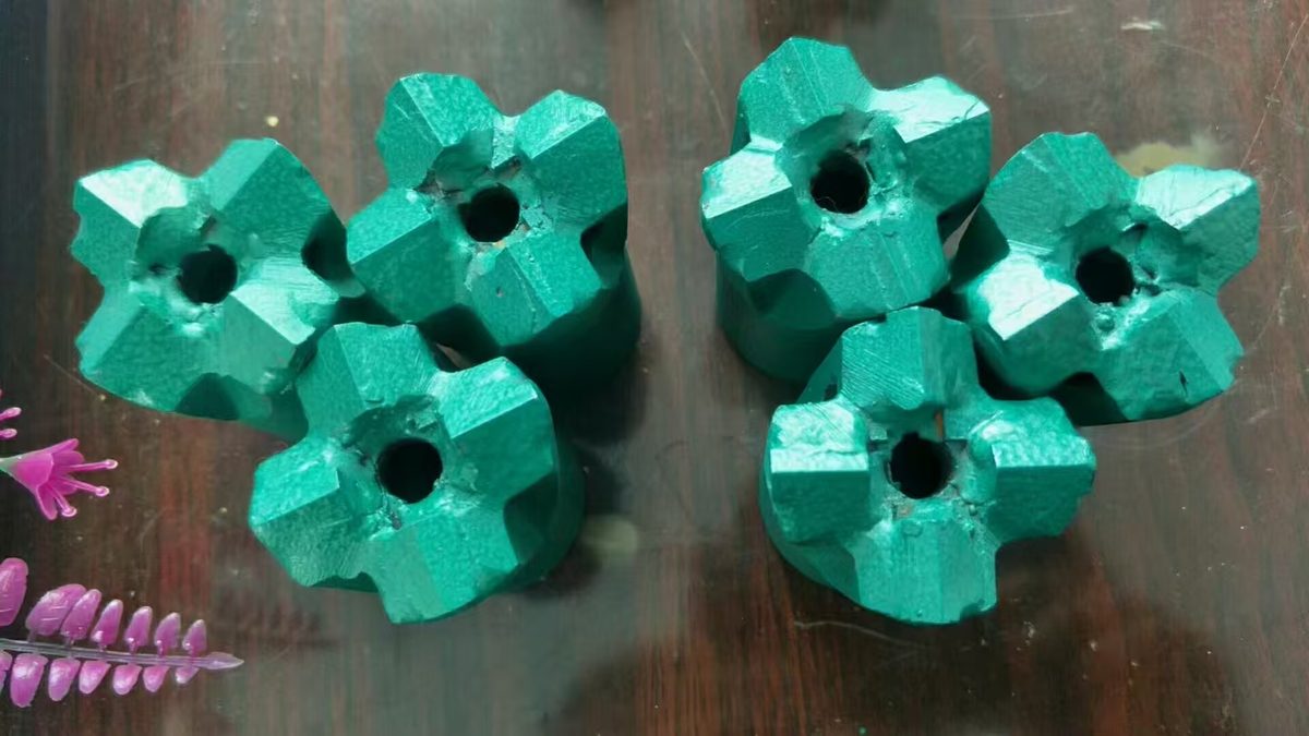
    Order the same bit twice from two suppliers and it can arrive black, green, blue, red or bare grey – sometimes from the same factory. A drill bit colour code is part of the specification, but it is the least reliable part, and knowing what it can and cannot tell you saves a whole batch from being used in the wrong ground.

    What the paint is really doing

    Underneath the colour, every painted bit has the same job list:

    • Corrosion protection. Drilling bits are steel and carbide, and they travel by sea. A primer or oxide coat keeps rust out of the thread and off the wing faces during months of storage and shipping.
    • Batch and diameter identification. In a plant where dozens of similar bits are made in one shift, paint separates a 45 mm from a 50 mm bit at a glance.
    • Grade or application marking. Some makers use colour to indicate which carbide grade or which coating a bit carries, or to separate bits intended for very different ground.
    • Customer marking. Private-label bits are frequently painted to a customer colour, and the colour carries no technical meaning at all.

    What colour cannot tell you

    There is no universal colour standard in the drilling industry. Green does not mean hard rock, and red does not mean soft rock, in any binding sense. Two suppliers can both ship green bits with completely different carbide grades, or ship identical bits in different colours. Treat colour as a hint, never as a specification.

    The same applies to oiled, waxed and bare-steel finishes. A heavily oiled bit is not automatically a better bit; it may simply be a bit that will sit in a warehouse for a year before it is used.

    What to check instead of the colour

    When a delivery arrives, the questions that actually protect you are mechanical:

    1. Gauge diameter – measured across the wing tips with a caliper, against the drawing.
    2. Wing symmetry – all wings the same length and profile, with no obvious casting or brazing defects.
    3. Carbide condition – buttons seated, no cracks, no visible gap at the braze line.
    4. Flushing hole – clear, round and on axis.
    5. Thread – clean, free from paint that has run into the flank, and seating properly on a known-good rod.

    Paint inside a thread is a small detail with a large consequence: it changes the fit and can cause a joint to work loose. If a bit arrives with paint on the thread, clean it before assembly. Our quality control checklist sets out the full receiving inspection, and this article on carbide tips explains what the insert itself should look like.

    Using colour the right way

    There are two sensible uses. First, as an internal discipline: many plants repaint a batch on receipt to mark the ground it is approved for – green for clay work, blue for lining, for example – and never mix the stock. Second, as a fast visual check that the right box has come to the rig. Both are house rules, and both only work when the rule is written down and the drawing travels with the part.

    If you are buying on colour alone – because a photo on a website looked right – you are buying the least informative part of the specification.

    Frequently asked questions

    Do painted bits drill differently?

    No. The paint is cosmetic and protective. Performance comes from the steel, the heat treatment, the carbide grade and the geometry.

    Should I remove the paint before use?

    Only where it interferes with a fit – threads, seating faces and the inside of the flushing bore. Leave the rest; it protects the steel.

    Will you match my existing colour?

    Yes. If your stock is coded by colour or you need private-label marking for your own customers, we match it on request – just send the reference colour and the dimensions that must be checked.

    Tell us the ground you are drilling and the diameter you need, and we will specify the geometry and carbide grade behind the colour – and paint it however your warehouse prefers.

  • Blast Furnace Taphole Cross Bits: Wing Geometry, Gauge and Flushing

    Blast Furnace Taphole Cross Bits: Wing Geometry, Gauge and Flushing

    Taphole drilling is the least forgiving drilling job in a steel plant. The bit has one pass, a hot and abrasive mix in front of it, and a schedule that does not wait. That is why the taphole cross bit looks so specific: every feature on it exists to solve one of the problems the hole presents.

    Start with what the bit has to cut

    A taphole is not a single material. Depending on where the bit is in the pass, it meets:

    • hardened tap-hole clay from the previous mud gun, which is abrasive and variable;
    • consolidated mud and coke fines near the bore;
    • the refractory lining itself, which is much harder and far less forgiving; and
    • occasionally solidified iron or slag, which is a different problem entirely.

    A bit that keeps a straight hole through all of that, at temperature, without wandering, is worth far more than its price. That is what the wing geometry is designed for.

    Wing geometry: why four and not two

    Four wings give the bit support in four directions at once. Instead of being pushed off line by a hard patch, the bit is held by the two wings on the opposite side. The result is a rounder, straighter hole and less side load on the rod.

    Three details of the wing matter more than the number:

    • Gauge diameter – the diameter swept by the wing tips. This sets the hole size and must stay consistent from bit to bit, because the mud gun and the tapping sequence are built around it.
    • Relief behind the cutting edge – the body behind each wing is relieved so that only the cutting edge rubs the wall. Without relief, friction and heat rise sharply.
    • Wing taper and rake – a steeper rake cuts faster in soft clay but is more fragile in the lining; a blunter rake lasts longer but needs more feed force.

    Flushing: the centre hole is not a detail

    The central flushing hole sits at the point where the wings meet. High-pressure water or air arrives through the rod bore, exits at the centre and travels back up the annular gap, cooling the cutting edges and carrying cuttings away. If that path is restricted, the bit heats up and the carbide goes quickly. Practical consequences:

    • Keep the rod bore clear – a partially blocked rod is the most common cause of a burnt bit.
    • Match water pressure to volume, not just pressure. High pressure with a thin stream cleans nothing.
    • Check the hole after every used bit comes off. A deformed or plugged centre hole is reason enough to retire the bit.

    Carbide selection for clay and lining

    Taphole work needs a grade that resists impact more than a grade that resists abrasion. The buttons or inserts are brazed or pressed into the wings, and brazing quality decides whether they stay there: a poor braze fails at the interface long before the carbide itself is worn out. When a bit comes back with buttons missing but almost no wear on the survivors, look at the joint, not the grade.

    Matching the bit to the rest of the string

    A taphole bit is only as good as the rod behind it. Thread form, bore diameter and rod straightness all affect how the bit behaves in the hole, and a worn rod thread will let the joint work loose under the vibration of the pass. It is worth reading our explanation of how cross-type bits cut taphole clay alongside this article, and if you are specifying the whole string, start from the basics of BF rods and bits.

    Frequently asked questions

    How often should a taphole bit be replaced?

    Replace on condition, not on a calendar: gauge still on size, wings not chipped, carbide present and the centre hole clear. Most plants retire a bit when the gauge drops below the size the tapping sequence needs.

    Is a three-wing bit ever better?

    Three-wing and three-button configurations exist mainly for button bit designs and can drill faster in some rock. In taphole clay the straightness and support of a four-wing bit usually wins – see the comparison in 3-button versus 4-button bits.

    Can a taphole bit be reground?

    The carbide can sometimes be re-profiled, but the wing tips are the gauge, so grinding them changes hole size. Treat regrinding as a specialist operation, not routine maintenance.

    Send us your taphole diameter, clay characteristics and opening machine details, and we will specify the wing geometry, gauge and carbide grade for your furnace rather than a generic catalogue bit.

  • Six Wear Patterns That Tell You What Went Wrong Down the Hole

    Six Wear Patterns That Tell You What Went Wrong Down the Hole

    Every worn bit is a report from underground, and learning to read drill bit wear patterns is the cheapest diagnostic tool a drilling operation can own. Each bit records the rock you drilled, how you drove the string, whether your flushing was working and whether your rods were straight. Most crews throw the evidence in the scrap bin. The crews with the lowest cost per metre keep a few retired bits on a shelf and compare them.

    Here are the six patterns that cover the great majority of failures, and what each one is telling you.

    1. Even wear across all buttons

    The good news pattern. Buttons are uniformly flattened, the body is intact, the gauge dimension is still close to nominal. Nothing is wrong except normal service – regrind and go again. This is what a well-set-up rig produces.

    2. Gauge worn, face still sharp

    The outer row is flattened or under size while the face buttons look almost new. Two causes:

    • The bit is being pushed sideways. Wandering hole, bent rod, poor collaring or misalignment between the feed and the hole axis.
    • The hole is over size for the string. Without wall support, the bit chatters and grinds its own gauge away.

    Fix the alignment before you buy more bits. Otherwise the replacement will wear the same way.

    3. Steel washout between the buttons

    The bit body is scoured and eroded and buttons sit on little islands of steel. This is a flushing failure, not a steel failure. High pressure with low volume, clogged flushing holes or an over-fast feed that packs cuttings against the face will all do it. Check the bore of every rod in the string, confirm the water or air volume, and slow the feed until the return flow is clean.

    4. Spalled or chipped carbide

    Pieces have broken off the button faces. Causes are usually one of: too hard a carbide grade for the impact energy, blunt buttons left too long so the load concentrates on a small area, or thermal shock from irregular flushing. Spalling is a pattern of neglect – it very rarely appears on a bit that was reground on time.

    5. Snapped or pulled buttons

    The whole button is gone and there is a hole where it was. That indicates impact far above design load: stalling the string, dropping the bit into a void, hammering on a stopped rotation, or drilling with a bit that had already lost its face buttons. Nothing about a snapped button can be blamed on the steel.

    6. Cracks, distortion and thread damage

    Hairline cracks through the shoulder, an oval body, flattened or galled threads. This is the end of the joint rather than the cutting edge, and it usually traces back to over-torque, cross-threading, or leaving wet joints assembled overnight. Our notes on coupling sleeve failure cover the same failure family on the rod side.

    Turn the pattern into an action

    Keep a simple log: bit number, metres drilled, rock type, and one word for the wear pattern. Within a few weeks a picture appears. If every bit arrives back with washout, nobody needs to argue about flushing any more; the inspection sheet already settled it. That is also how you build a defensible replacement interval, and how you decide whether to buy a longer-life bit or a cheaper one – see our guide to wear forms and service life.

    Frequently asked questions

    Which wear pattern is most expensive?

    Washout and under-size gauge wear. Both make you slow down without any single visible failure, so the cost arrives as lost metres rather than a broken part.

    Should I keep worn bits?

    Keep two or three per ground condition as reference samples, and scrap the rest. A shelf of labelled reference bits is the cheapest training tool a drilling team can own.

    Can wear patterns prove a supplier is at fault?

    They can point strongly one way or the other. Uniform wear and correct geometry point at service conditions; porous or badly brazed carbide, off-centre wings or soft heat treatment point at manufacture. That is why a documented inspection routine on receipt matters as much as a post-mortem.

    Send us photos of your retired bits – face, gauge and shank – with your rock type and hole diameter, and we will tell you which pattern dominates and what to change first.

  • Button Bit Regrinding and Wear: Gauge Buttons, Face Buttons and When to Sharpen

    Button Bit Regrinding and Wear: Gauge Buttons, Face Buttons and When to Sharpen

    A button bit does not wear evenly. The carbide on the face does the work, but the row of buttons around the outside holds your hole size – and that outer row almost always decides when the bit has to come off the rig. Understanding the two jobs separately is the difference between a bit that is reground three times and a bit that is thrown away while it still had life in it, so button bit regrinding starts with knowing which row is worn.

    Two families of buttons, two different jobs

    Face buttons sit on the front of the bit and crush the rock as the hammer strikes. They wear on their tips, gradually flattening into small facets. Flattened face buttons do not cut; they rub, heat up and slow the whole string down.

    Gauge buttons sit in the outer row and follow the wall of the hole. They are responsible for keeping the hole to diameter and for steering the bit straight. When they wear, the hole diameter shrinks. The rod then drags on the wall, flushing gets worse, and the next bit has to open a hole that is already under size.

    Button shape matters too: spherical buttons are the toughest and suit hard, abrasive rock; ballistic and conical buttons penetrate faster in softer or more brittle ground but wear away sooner. Mixing button shapes within one bit is normal – the shape is chosen for the load that row carries.

    Reading the wear before you decide

    • Flat facets on face buttons: normal wear. Regrind restores the dome and brings penetration back almost to new.
    • Gauge buttons worn below the face buttons: the bit is about to drill under size. Measure the outer diameter across the gauge buttons, not across the body.
    • Steel washout between buttons: the body has eroded, usually from poor flushing or too much water pressure with too little volume. This is not recoverable by grinding.
    • Snapped or missing buttons: an impact problem – too much feed force, a stalled string or a hole full of cuttings. Also not recoverable.

    When regrinding is worth it

    Regrind while the buttons still have height. A widely used working rule is to grind when the flat on a button reaches roughly one third of its diameter, and to stop regrinding when button protrusion falls below about 3 mm or the steel around the buttons starts to erode. Every grind removes carbide, so a bit has a finite number of lives – usually two or three.

    Do it properly: use a diamond wheel, keep the coolant flowing, restore the original dome profile rather than simply skimming the flat, and let the button cool slowly. Overheated carbide cracks within a hundred strikes, which costs more than the regrind ever saved.

    The economics nobody writes on the invoice

    An unsharpened face button typically cuts penetration rate by a noticeable margin within a few hundred metres, and penetration rate is what drives your cost per metre: rig time, wage, fuel and depreciation all run at the same hourly rate whether the bit is cutting or rubbing. Regrinding a bit usually costs a small fraction of a new one. If it restores even ten percent of penetration for the rest of the bit’s life, it has paid for itself.

    Frequently asked questions

    How do I know if a bit is worn out rather than worn?

    Measure the gauge. If the outer row has taken the diameter below the tolerance your hole requires, the bit is finished regardless of how the face looks.

    Can I regrind a bit myself?

    You can, with a proper button bit grinder and the correct diamond cup wheel. Doing it with a hand grinder usually overheats the carbide and leads to early button loss.

    Why do my gauge buttons wear faster than the face?

    Usually because the hole is wandering or the string is not straight, so the bit is being pushed sideways into the wall. Check rod straightness and alignment – the causes are the same as those in the five on-site causes of bit breakage.

    Tell us the rock, the hole diameter and the rig, and we will recommend the button shape and gauge configuration that lasts longest in your ground – and the regrind interval that goes with it.

  • Drill Rod Coupling Sleeves: Why They Fail and How to Make Them Last

    Drill Rod Coupling Sleeves: Why They Fail and How to Make Them Last

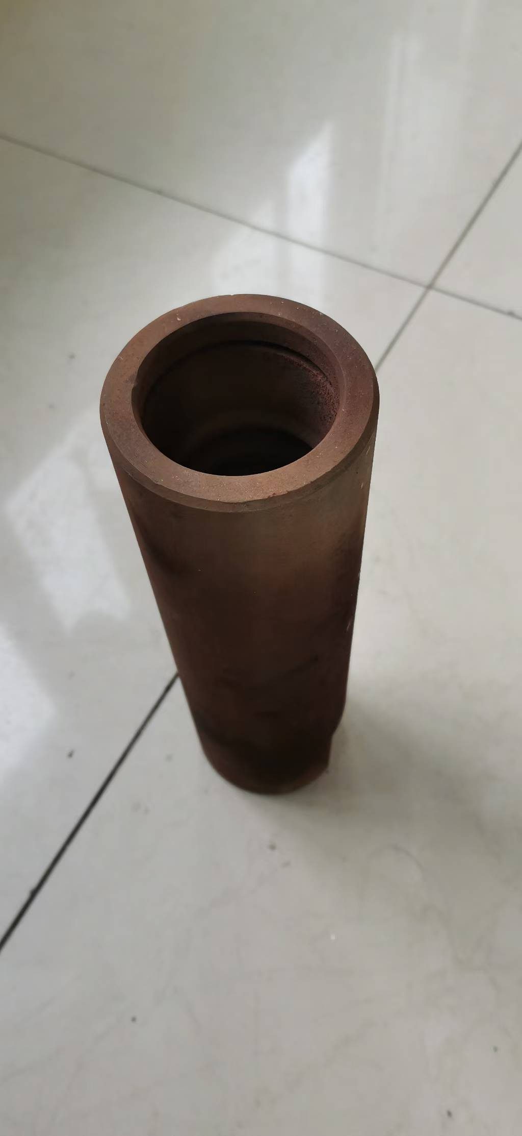
    Ask a drilling crew which part of the string they think about least and the answer is usually the coupling sleeve. Ask them which part caused the last unscheduled stop, and the answer is often the same. The sleeve is a short, heavy-walled piece of steel with a thread at each end, and it carries every bit of torque, thrust and bending that the rod string generates.

    What a coupling sleeve actually does

    When rods are joined end to end, the sleeve is the joint. It has to do three jobs at once: transmit torque without slipping, carry impact thrust through its shoulders, and stay straight enough that the string does not whip. Because it is short and thick, it is also the stiffest part of the string – which is exactly why it takes the bending load when the hole wanders.

    The four ways sleeves fail

    1. Thread wear. Repeated make-and-break cycles slowly polish the flanks. The joint starts needing less torque to break, then begins to work under load, and the wear accelerates.

    2. Distortion. Over-tightening, or driving with a bent rod behind it, ovals the sleeve body. An oval sleeve binds in the hole, creates friction and overheats.

    3. Cracking at the shoulder. A hairline crack starts at the transition between the thread and the shoulder – the classic stress riser. It grows quietly until the sleeve splits.

    4. Corrosion pitting. Water sits in the thread root overnight, pitting starts, and fatigue then finds the pit. This is a storage and housekeeping failure, not a steel failure.

    Why sleeves fail early

    In our experience the causes are predictable, and only one of them is about quality:

    • Cross-threading during a hurried change, which removes the protective surface from the first thread turn.
    • Mismatched hardness. A very hard sleeve against a softer rod thread transfers all wear to the rod, and the reverse destroys the sleeve. Joints should be matched as a pair.
    • Running past the recommended depth for the string, so bending loads rise sharply.
    • Leaving joints assembled and wet, which turns a consumable into a rusted-together assembly.

    Five habits that double sleeve life

    1. Brush and inspect both threads before every change – five seconds against a whole shift.
    2. Tighten to the correct torque, with the correct wrench, and mark the joint.
    3. Break joints at the end of the shift, not the start of the next one.
    4. Store sleeves on a rack, threads oiled, away from the ground.
    5. Retire a sleeve at the first shiny thread band or any visible crack. It costs less than a lost hole.

    Checking a sleeve in ten seconds on the rig floor

    Roll it across a flat plate: any wobble means distortion. Look down the bore against the light: pits and rust rings mean water has been sitting inside. Then screw it onto a known-good rod by hand. If it will not turn freely for the first three turns, it is already damaged, no matter how it looks.

    Frequently asked questions

    Are all coupling sleeves the same steel?

    No. Sleeves are usually made from a hardened alloy steel and then heat treated to match the rod thread they will work with. Buying a generic sleeve for a specific rod string is a false economy – see how heat treatment and machining affect these joints.

    Can a sleeve be reused after regrinding the thread?

    Practically, no. Once the thread is recut, the sleeve no longer matches the drawing, and the joint load moves to the wrong faces. Replace rather than repair.

    How many make-and-break cycles should I expect?

    It depends on ground, torque and housekeeping far more than on the number itself. Track it: note when you retire a sleeve and how deep the string went. Within a month you will know your own realistic service interval, and you can plan replacements instead of reacting to failures.

    We supply rods, bits and matching coupling sleeves as one system, so every thread in your string is made to the same drawing. Tell us your rod size and thread, and we will quote the sleeves that go with it.

  • Threaded Shank Bits and Rods: How to Match Threads Without Guessing

    Threaded Shank Bits and Rods: How to Match Threads Without Guessing

    When a threaded joint fails, it rarely fails dramatically. It loosens a little, heats up a little, and then one day the bit is gone down the hole and the shift is over. Almost every one of those failures starts with a thread that never matched properly in the first place.

    Why threads fail before the bit does

    A threaded shank carries the entire drilling load through a few square centimetres of contact. Four things go wrong:

    • Cross-threading during a hurried change on a dusty rig floor. The first turn decides the life of the joint.
    • Under-tightening so the faces never seat. The joint then works, frets and wears.
    • Bottoming on the thread instead of on the shoulder, which leaves the load on the thread flanks rather than the machined faces.
    • Galling and corrosion, especially when a hot, wet joint is left assembled overnight.

    The three thread families you will meet

    Most bits and rods on the market fall into one of three groups:

    • Taphole threads. Short, deep trapezoidal threads designed for blast furnace opening machines, where the joint must be made and broken many times a day under high temperature.
    • Drifting and tunnelling threads. The familiar R and T families – R32, R38, T38, T45, T51 – used on long-hole and face drilling equipment. They are larger, with a distinct shoulder that carries the impact.
    • General machine threads. Metric or inch threads found on light rotary rigs, augers and specialist machines. These are dimensioned by the machine builder, not by a drilling standard, so they must be measured rather than assumed.

    Two threads can look identical on a rig floor and still be incompatible. Never match by eye and never match by name alone – R38 from one supplier and R38 from another can differ in shoulder geometry.

    Measure these five things before you order

    1. Pitch and major diameter – measured with a thread gauge or pitch gauge, not with a ruler.
    2. Shoulder angle and form – the machined face that takes the thrust.
    3. Usable thread length – too long and the joint bottoms on the thread; too short and there is not enough engagement.
    4. Hand of thread – most drilling joints are right hand, but left-hand joints exist on some machines and reverse-rotation applications.
    5. Taper of the seating face – some designs seal and centre on a cone behind the thread.

    If you cannot measure, borrow the drawing. Our rod and bit matching guide shows which dimensions to photograph and send to a supplier so the parts are made to match, first time.

    Assembly practice that doubles joint life

    Clean both threads with a wire brush, wipe them dry and apply a light film of thread lubricant or copper-based grease. Start the joint by hand until it runs freely, then tighten with the correct wrench – firm, not brutal. Mark the joint with a paint stripe so you can see at a glance whether it has backed off. Break the joint while it is still warm rather than leaving it overnight, and never use a stillson wrench on a drilling thread.

    Warning signs of a thread about to let go

    • A polished, shiny band across the thread flanks where metal has fretted.
    • A joint that needs noticeably less torque to break than it did last week.
    • Thread crests rolled over or flattened instead of sharp.
    • Rust staining or pitting inside the female thread, a sign of water sitting in the joint.

    Frequently asked questions

    Can I repair a damaged drill thread?

    Only by re-machining to the original drawing and re-heat-treating the affected zone, which is rarely economic for a consumable. A dressed-up thread that no longer matches the standard is more dangerous than a worn one, because it will pass a visual check.

    Do I need a torque wrench?

    For small hand-held equipment, no. For larger drifting joints, a torque spec from the manufacturer is worth following: too little damages by fretting, too much damages by cracking the shoulder.

    Should bits and rods come from the same supplier?

    It removes an entire class of problem. Threaded joints are a system, and a supplier who makes both ends can guarantee the fit – see our drill rod selection guide for what to specify.

    Send us a photo of your thread profile next to a rule, and we will identify it from the pitch and shoulder form and quote bits and rods that fit together as one system.

  • Tapered Drill Rods: 11 vs 12 Degree Taper and How to Choose the Right One

    Tapered Drill Rods: 11 vs 12 Degree Taper and How to Choose the Right One

    A tapered drill rod is the simplest connection in rock drilling: no threads to cross, no torque to set, just a machined cone that wedges the bit onto the rod. That simplicity is also why tapered rods are so easy to get wrong. Buy a rod whose taper does not match your bits and you will spend the shift re-fitting bits instead of drilling.

    What makes a tapered rod different

    Instead of a threaded joint, a tapered rod carries a male cone at the bit end and a matching female cone at the shank end. The bit is pushed on and held by friction plus the thrust of the hammer. Changing a bit takes seconds, which is why tapered equipment still dominates hand-held drilling, secondary breaking, dimensional stone and light bench work.

    Three dimensions define a tapered rod: the shank that fits the hammer, the taper at the bit end, and the length and diameter of the rod body itself.

    11 degree or 12 degree taper: what the number really changes

    Both angles are used in the field. The difference is how the cone behaves under load:

    • 11 degree tapers are shallower, so the contact area between rod and bit is larger. They grip firmly and are common where bits must stay put under heavy thrust and long collaring.
    • 12 degree tapers release more easily. That suits operations where bits are changed constantly, for example when a driller works through several rock types in one hole.

    What matters far more than the number is consistency: a 12 degree bit on an 11 degree rod (or the reverse) will either never seat or will hammer itself loose, damaging both parts. Never mix taper angles inside one drill string, and never buy bits and rods from different sources without a gauge check.

    Choosing shank, diameter and length

    The shank is dictated by your hammer, not by preference. Light hand-held rock drills commonly take a 22 mm hexagon shank (22 x 108 mm); heavier hand-held and light wagon drills often take a 25 mm hexagon shank (25 x 159 mm). Round shanks appear on some machines and on rods intended for rotary work.

    Rod diameter follows the hole and the rock: a thicker rod is stiffer and straighter in broken ground, a thinner rod is lighter and cheaper to run in soft formations. Length is usually chosen from a standard ladder – commonly 0.6 m to 3.2 m – and the rule is to drill with the shortest rod that reaches the required depth, because rod whip grows with length.

    Inspecting a tapered rod before you trust it

    Half of all taper problems are visible in daylight:

    • Taper surface: look for bright polished rings, scoring or a visible shoulder inside the female cone. A worn female taper is the most common reason a bit falls off.
    • Straightness: roll the rod on a flat surface. A rod that wobbles will drill an oversized, drifting hole.
    • Shank: check for hammer marks, cracking at the collar and ovality where the chuck grips.
    • Flushing bore: blow through it. A blocked rod bore overheats the bit within minutes.

    Handling rules that pay for themselves

    Never hammer a bit onto a taper, and never use the bit itself as a drift to break the joint. Keep the cones clean and lightly oiled, store rods on racks rather than on the ground, and retire a rod the moment the taper shows a shoulder. A rod is a consumable; a hammer is not.

    Frequently asked questions

    Can I use a threaded bit on a tapered rod?

    No. Tapered and threaded are two separate connection systems. The joint must match end to end, which is why we recommend ordering rods and bits together – see our matching guide.

    How long should a tapered rod last?

    Life is governed by the taper and the shank, not the body. In abrasive rock, expect the taper to wear out long before the steel does. Keep a spare rod and a spare bit on the rig so a worn taper never stops the shift.

    Which steel is best?

    Chromium-molybdenum grades such as 42CrMo are the usual choice for rods that see impact and bending, with plain carbon-manganese grades for lighter duty. We compare them in 42CrMo vs 40Cr drill rod.

    Tell us your hammer model, hole diameter and the rock you are drilling, and we will specify the taper, shank and length that keep your bits tight and your metre rate high.

  • Cross Bit vs Button Bit vs Chisel Bit: Which One Do You Actually Need?

    Cross Bit vs Button Bit vs Chisel Bit: Which One Do You Actually Need?

    Open any drill bit catalogue and three shapes look back at you: the four-wing cross bit, the domed button bit and the flat chisel bit. They are not interchangeable, and picking the wrong one is one of the fastest ways to turn a cheap-looking purchase order into expensive downtime. This guide compares the three in plain terms: what each shape does, which ground it suits, and how to decide in five minutes on site.

    The three shapes in one sentence each

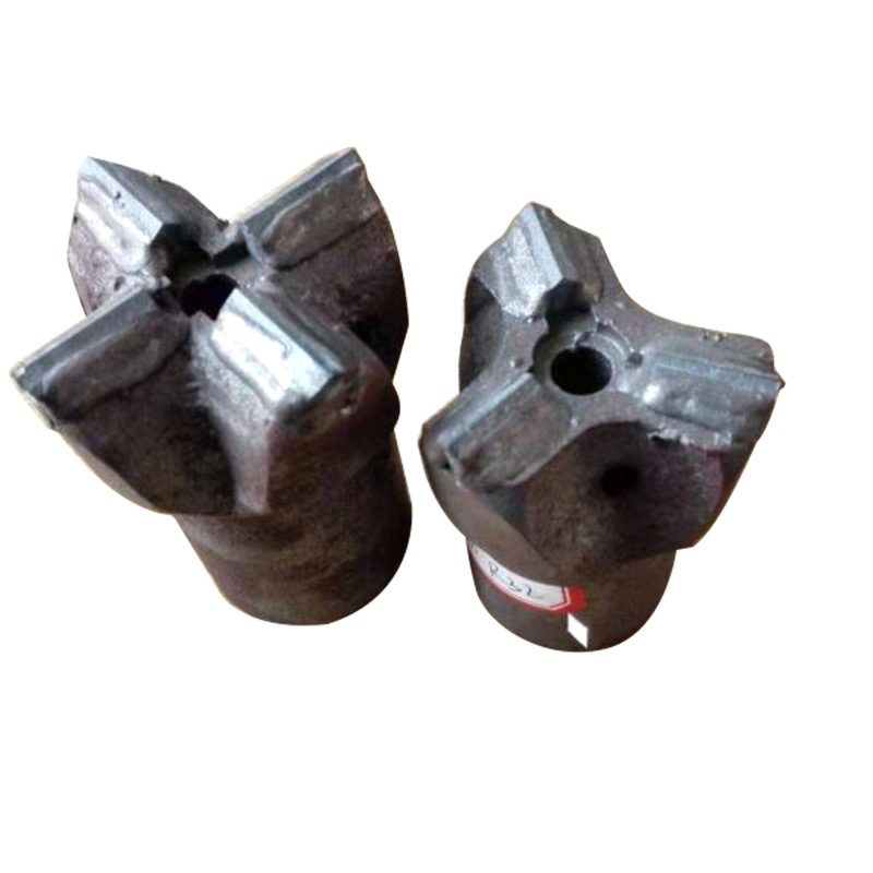
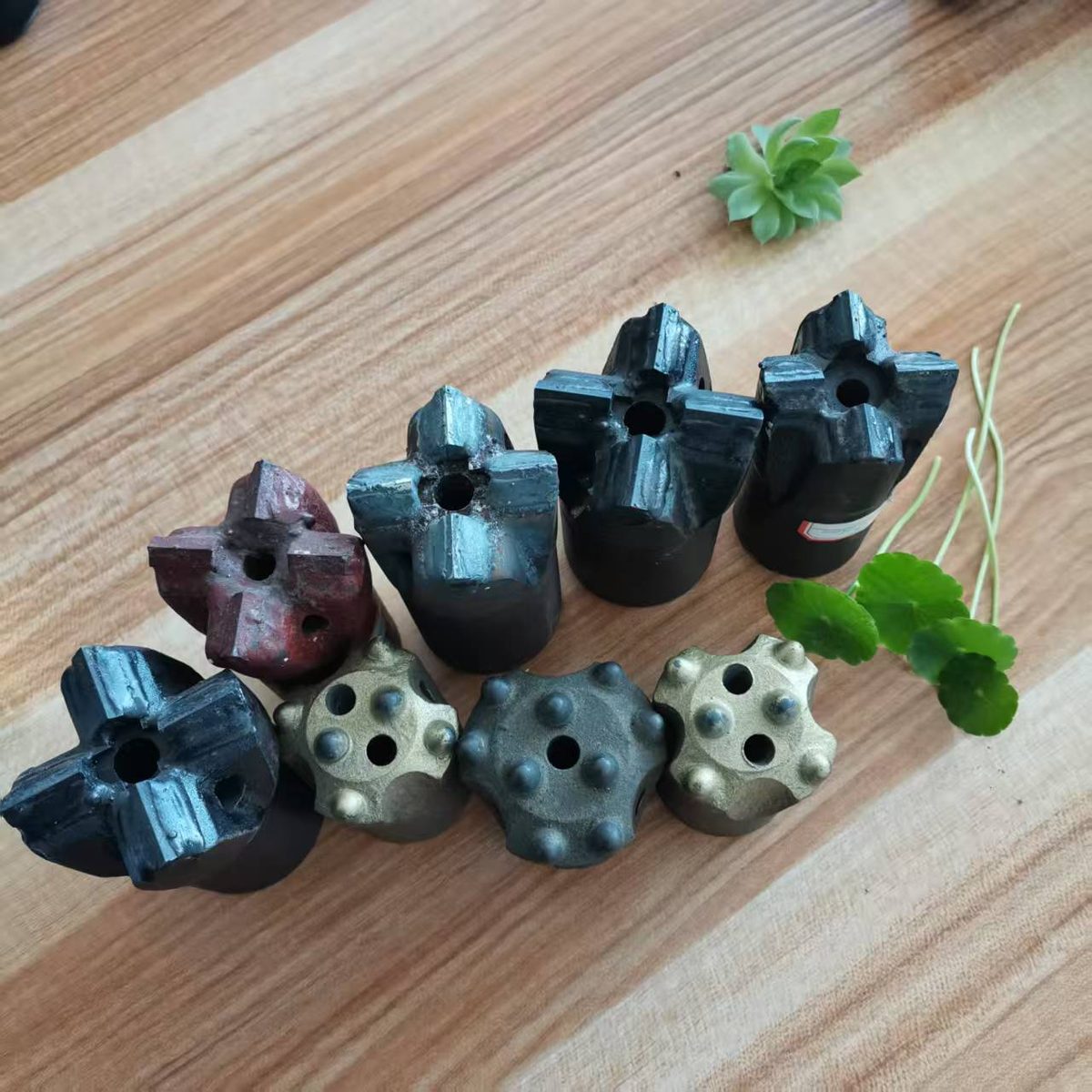
    Cross bit. Four cutting wings arranged like a plus sign, with tungsten carbide inserts or buttons set into each wing. Because the wings bite in four directions at once, the bit centres itself and drills a straight, round hole. It is the classic choice for blast furnace taphole clay, where you have to reach a precise point in the lining in a single pass.

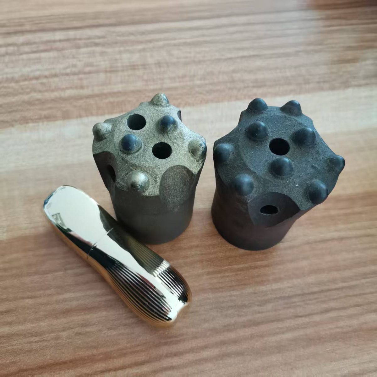
    Button bit. A domed or flat face studded with hemispherical carbide buttons. Instead of shaving the ground, the buttons crush it under impact and rotation. They can be reground several times, which is why button bits dominate hard, abrasive rock such as granite, basalt and hard limestone.

    Chisel bit. One straight cutting edge, or a cross of two chisel edges, at the tip. Simple, inexpensive and quick in soft to medium ground such as clay, shale, coal and soft sandstone. It will not last in hard rock, and in bedded formations it tends to follow the seam instead of drilling where you aimed.

    How to choose in five minutes

    Ask four questions, in this order.

    • How hard is the ground? Soft clay, mud-gun mix or coal points to a chisel bit or a light cross bit. Medium rock points to a cross bit. Hard, abrasive rock points to a button bit.
    • Does the hole have to be straight and on size? If yes – taphole drilling, anchor holes, any hole that must line up with a second hole – the four-point support of a cross bit is worth more than raw speed.
    • What is driving it? Impact energy, rotation speed and flushing pressure set the limit on what a bit can take. A bit built for a light hand-held hammer will chip quickly behind a heavy drifting rig.
    • How much can you afford to stop? Button bits cost more per piece and less per metre in hard rock. Chisel bits cost less per piece and, almost everywhere else, more per metre.

    Matching the bit to the rod is the other half of the job

    Shape is only the first half of the decision. The second half is the connection: shank profile, thread type, diameter and length must all match the rod string, or the bit will either refuse to seat or work loose under vibration. If you are ordering both parts at once, start with our thread, diameter and length matching guide and take the measurements before you take the price.

    Three mistakes we see every week

    1. Button bits in clay. With nothing abrasive to keep them sharp, the buttons on a new button bit cannot bite into wet taphole clay. The bit spins, heats up and polishes instead of cutting. A cross bit does the same job for a fraction of the price.

    2. Chisel bits in hard rock. A chisel edge in granite rounds off within metres and then does little except generate heat. If the rig gets louder without penetrating faster, stop and look at the bit.

    3. Mixing wear states in one string. A new bit behind a worn one, or a worn bit behind a new one, bends the rod string. Both lives get shorter. Keep matched sets together.

    Frequently asked questions

    Is a cross bit the same as a four-wing bit?

    Yes. Cross bit, four-wing bit and four-point bit describe the same family. Suppliers use the terms loosely, so always confirm the drawing rather than the name.

    Can a button bit be resharpened?

    Usually two or three times, provided there is still enough button height and no body washout. Once the gauge buttons are under diameter or the steel around them is eroded, regrinding only delays the replacement.

    Which bit gives the cheapest hole?

    Almost never the cheapest bit. Compare cost per metre including rig time: a bit that costs twice as much and drills three times as long is the better purchase. We show the arithmetic in our cost per metre guide.

    Whether you open a blast furnace taphole twice a shift or drill anchor holes underground, the right answer is the bit that matches your ground, your rig and your deadline. Send us the rock description, the hole diameter and a photo of the bit that failed last, and we will tell you which of the three shapes fits – and why. Browse the full range on our news and product pages.

  • What Are Blast Furnace Drill Rods and Bits? An Intro to the Core Tools of Tap-Hole Drilling

    What Are Blast Furnace Drill Rods and Bits? An Intro to the Core Tools of Tap-Hole Drilling

    In blast furnace ironmaking, a channel must be drilled through the blast furnace tap hole before each tapping to let the hot iron flow out. The tools that perform this job are the blast furnace drill rod and the blast furnace drill bit. Many new operators and buyers only see them as "a steel pipe with a tungsten-carbide head," yet they directly determine tapping time, smooth iron flow and work safety.

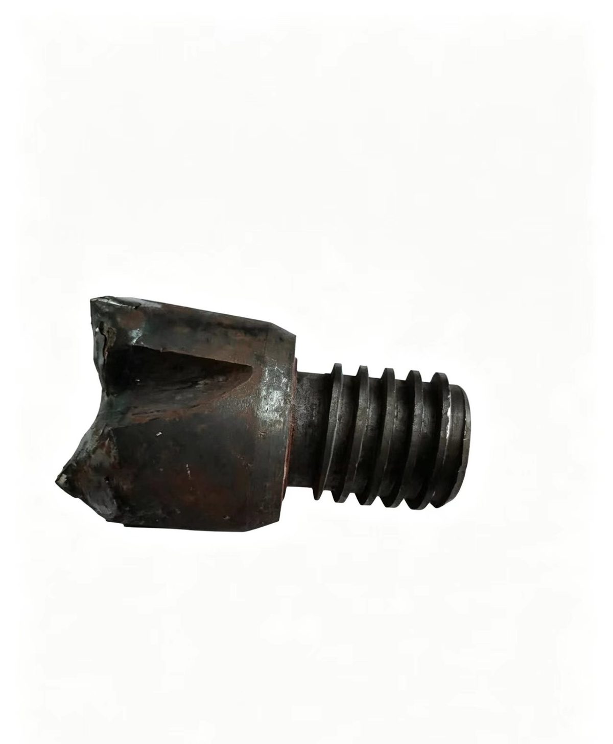
    The drill rod connects the opening machine's power end to the bit. It usually has a central bore for high-pressure cooling water or compressed air, and its ends are joined to the next rod or to the bit by special trapezoidal threads. The bit sits at the very front of the string, directly crushing the tap-hole clay, refractory material and a certain depth of solidified lining. It is the most severely worn and highest-impact part of the whole string.

    Compared with water-well or geological drill rods, BF drill rods and bits work under far harsher conditions: the drilling point sits close to the steel shell with high ambient temperature; vibration and shock are severe; and once a bit sticks in the tap hole, removal is difficult and may disrupt the tapping schedule. That is why BF drill rods use dedicated steel grades, wall thicknesses, thread precision and heat treatment, while the bit's carbide grade and brazing process must match the clay hardness and lining material.

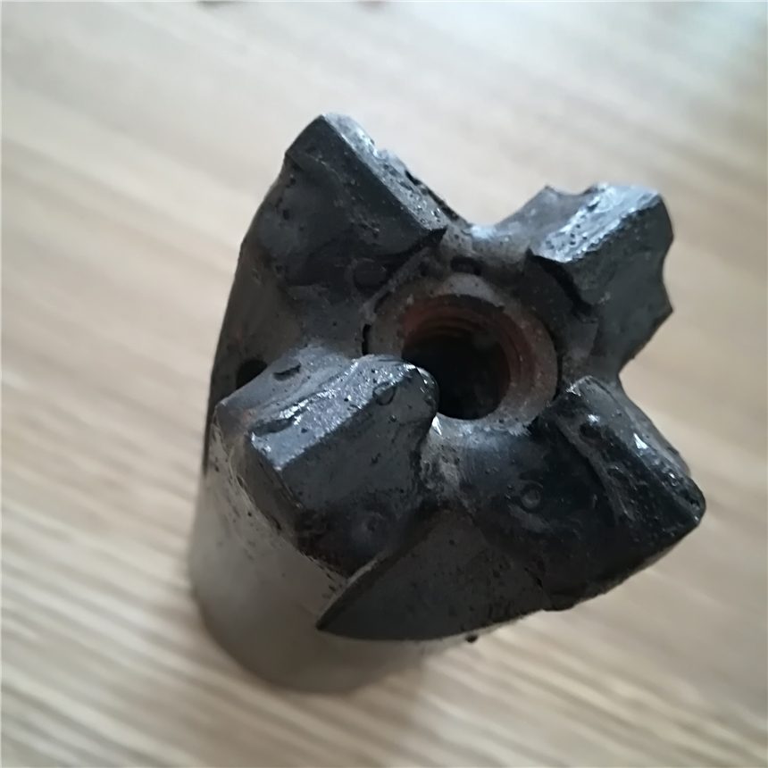
    A qualified BF drill rod should be straight, free of obvious bends, with clean crack-free threads. A qualified bit should have symmetric cross wings, firmly seated carbide buttons and an open flushing hole. Choosing and using these two tools well is what every BF operator and buyer cares about most.